[ Community Forums ] [ Products ] [ Docs ] [ Downloads ] [ History ]
The Morlock board is not specific to any paintball marker so will always need some customization to install.

There are three ways to power the morlock board:
- LiPo plugged directly into the board through the on-board plug.
- Plugging in a USB will power the board on (in addition to charging the LiPo, if attached)
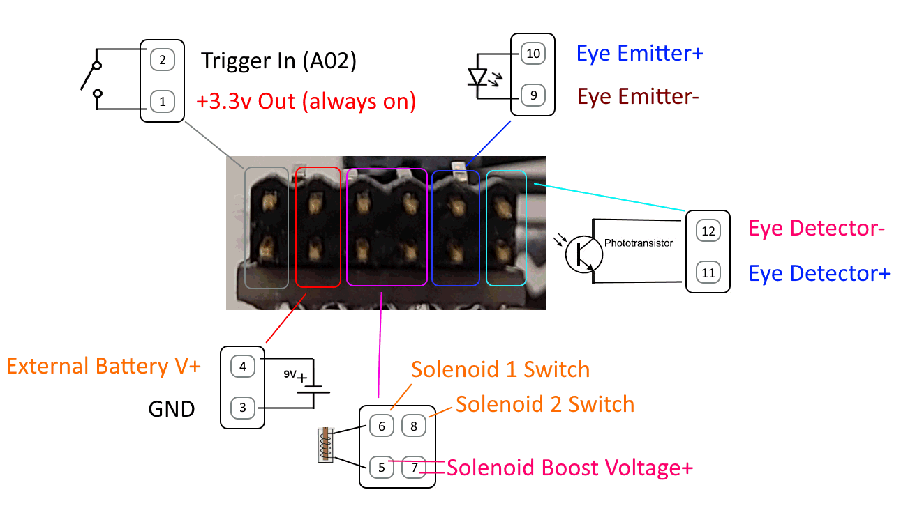
- External battery, any voltage from 4v to 18v, through the header (Pin 3+4 shown above)
Note 1: The on-board connector can only have a LiPo attached, because the board will attempt to charge it whenever plugged into USB.
Note 2: The Morlock board protects from being powered from multiple sources, all three can be plugged in simultaneously, the highest voltage will be selected automatically.
The Morlock board can be powered on/off in two ways:
- It will automatically power-down after 5 minutes, the trigger wakes it up.
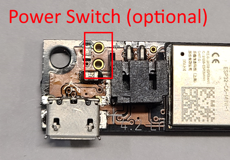
- A momentary button can connect the 'sleep' switch contacts that will power the board on/off
The Morlock watches pin 1+2 for the trigger. Connect the trigger switch between these two pins.
Advanced Users:The actual "input" is pin 2, which is active HIGH. pin 1 is the 3.3v output from the on-board voltage regulator. This voltage is always on even when the board is fully asleep so the trigger can wake the board up.
Connect Solenoid 1 between pin 5 and 6. Connect Solenoid 2, if used, to pin 7 and 8.
In single-solenoid use pin 8 becomes an "accessory" switch. Run the negative side of the accessory motor to pin 8 to be switched to ground.
Internally the Emitter has a 440-ohm current-limiting resistor, while the detector has a 4.7K pulldown to ground.
Please double check the polarity!


The 4-pin 90-degree header on the morlock board is labeled underneath, the only place it fit.